|
|
For
participants only. Not for public distribution.
|
 |
Note #6
John Nagle |
Introduction
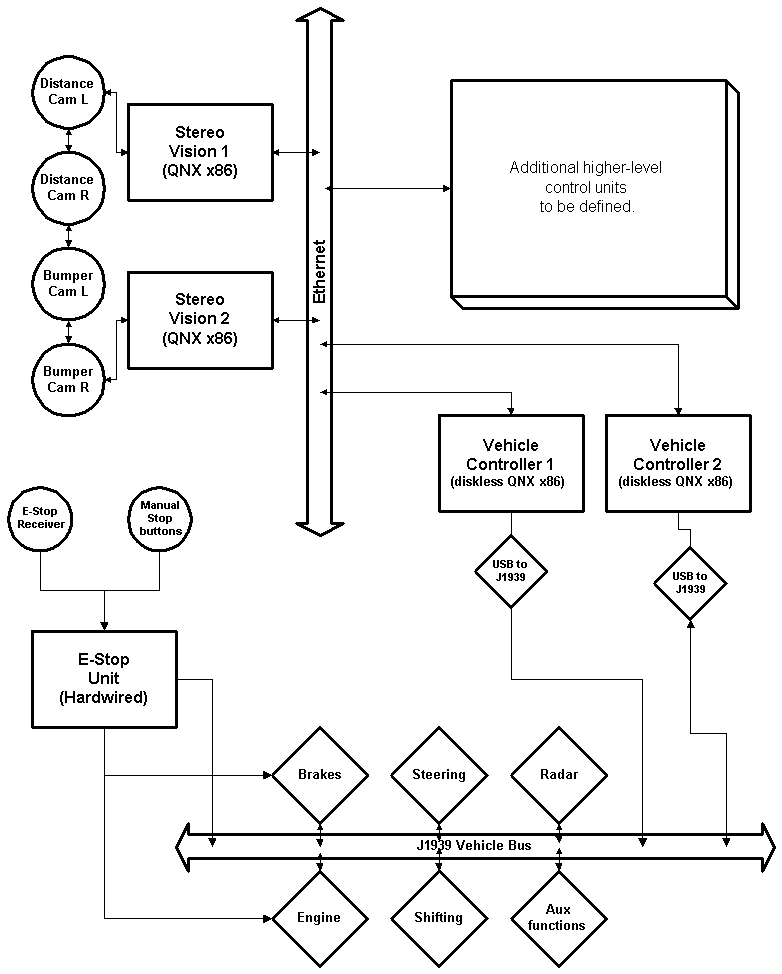
We're now far enough along to take a first cut at a system block diagram.
 |
|
System
architecture overview - preliminary
|
Component notes
Emergency stop unit
One of the few things we'll have to build.
The E-stop unit forces the vehicle to stop. When triggered, it must immediately force a brake application by electromechanical means, probably a motor-driven ballscrew attached to the brake linkage through a spring. It must kill the engine. And it must cause a signal to appear on the J1939 bus indicating that an E-stop has been triggered.
E-stops have to be considered a part of normal operation, because a loss of signal will trigger them. We have to be able to restart remotely from an E-stop, so once the E-stop device has been reset via the E-stop receiver, the control computers are allowed to restart everything.
The E-stop unit must also contain a watchdog timer, reset every 100ms or so over the J1939 bus by the vehicle control computers.
The J1939 bus interfaces to the emergency stop unit should be through off-the-shelf contact-closure to J1939 bus interface units.
Vehicle controller computers
These machines close the major vehicle control loops. They run-time-critical code. They should have as little state as possible. These will be small machines, probably diskless with flash memory. Industrial, ruggedized x86 machines running QNX, most likely. They handle the vehicle interface on the J1939 bus, and talk to the higher-level controllers via Ethernet. (Duplicate the Ethernet? Probably.)
One computer will run as primary and the other as standby, ready to take over if the first computer stops sending watchdog timer messages.
Vision computers
The front end of the stereo vision process (and, let us not forget, road-following) is compute-intensive. These machines get images from the cameras and do the basic stereo computation. They'll probably be too busy to do much else.
We'll need at least two sets of cameras, as previously discussed; one for long distance, and another in the front brush guard to peek over hill crests. We should be able to operate with either set of cameras down or obscured, at reduced speed. When the sun is near the horizon, if we're facing towards the sun, the distance cameras are likely to be blinded. But we can move forward slowly on the front cameras, which look downwards. If we lose the use of the front cameras to dirt or damage or brush, we can still crest a hill at creeping speed, using microwave distance sensors (usually used as backup warning devices) pointed downward in the front bumper to check for cliff edges.
Cameras are all FireWire, so we could, potentially, let one vision computer use the other's cameras by suitable FireWire networking. The additional complexity probably isn't worth it; we're more likely to lose cameras than computers. It's probably more useful to put the effort into being able to move forward on a single set of cameras when necessary.
Higher-level control
Higher-level control will be addressed later. That's where the mapping, planning, and decision making is done. Those machines have no exotic interfaces; they just talk to the LAN.