|
|
For
participants only. Not for public distribution.
|
 |
Note #36
Khian Hao Lim |
The following is the first formal description of the data and power connections present on the vehicle (chassis and backbed) for the computers and sensors.
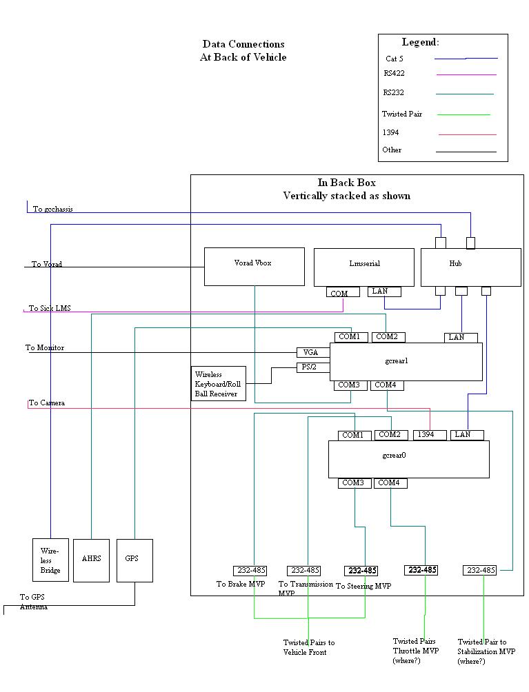
Back Bed Data Connections Diagram
There is limited space in the back box. We would stack the rear computers at the bottom, separated by sponge. The Vorad Vbox, ethernet serial server (lmsserial) and industrial hub will be stacked on top. We would fill it up with more separation and the sponges will be compressed keeping the equipment in place when the lid is closed. The wireless bridge is left in the diagram and would be present during testing and absent in competition version. The rs232 to rs485 converters have rs232 connections on one end that will go into the rear computers and terminal blocks on the other end that leads to twisted pairs that go to the MVP units. They are port powered and so will not need their own power.
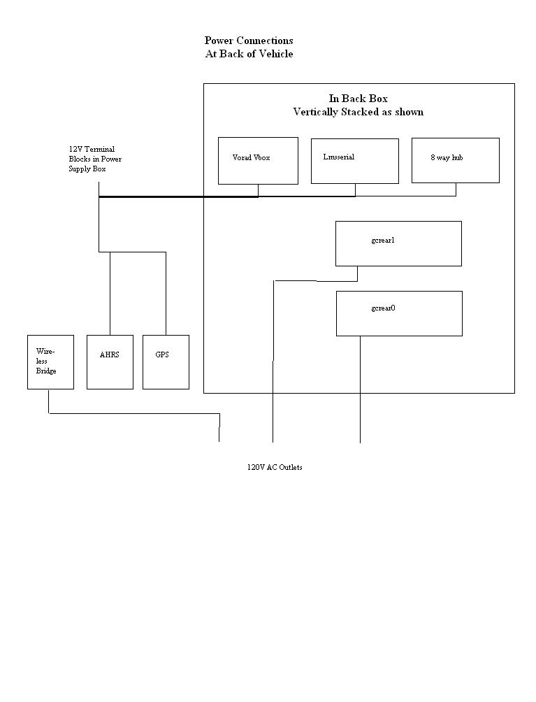
Back Bed Power Connections Diagram
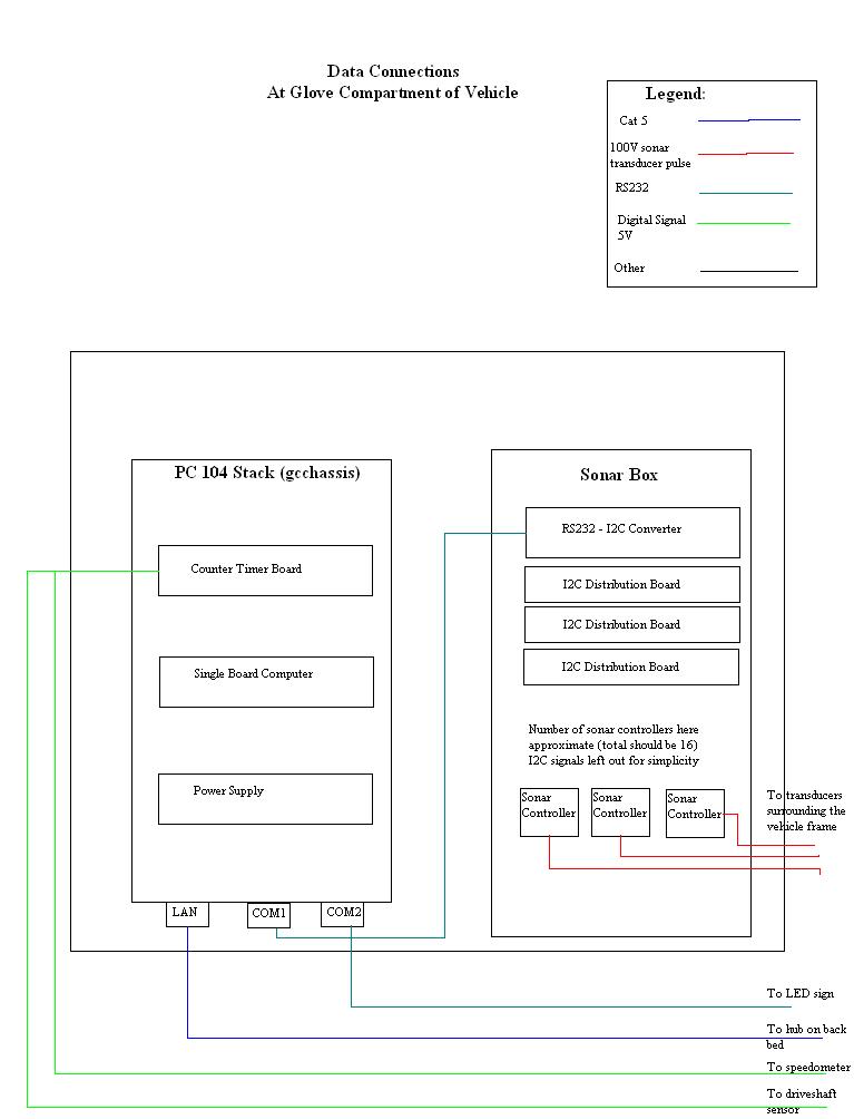
Glove Compartment Data Connections Diagram
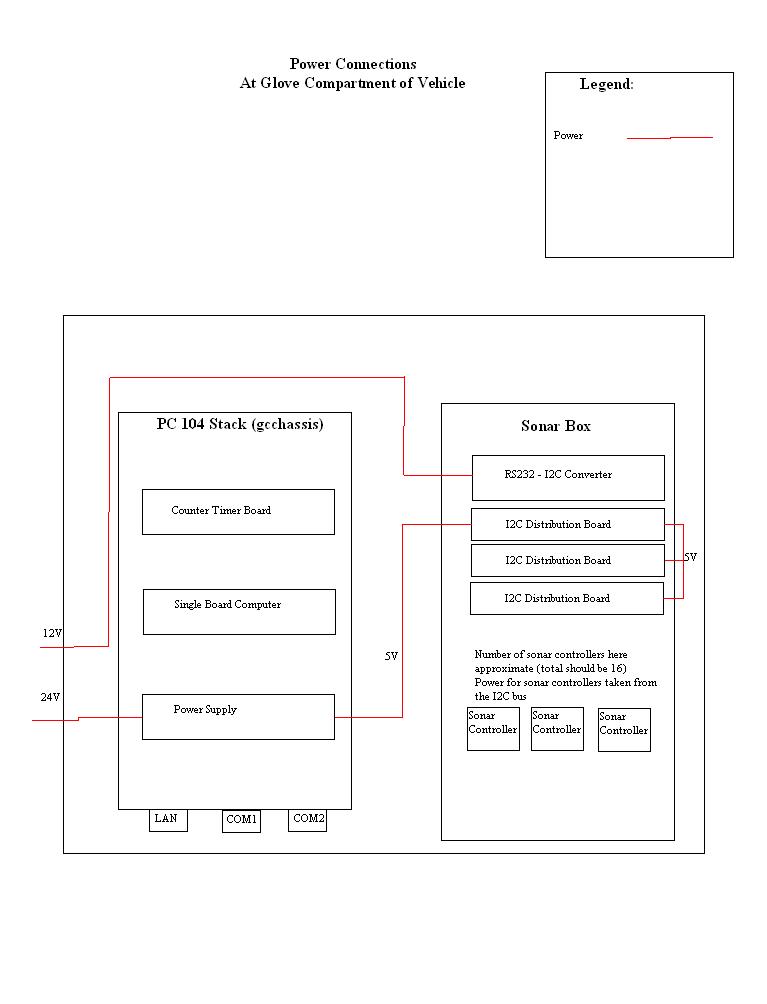
Glove Compartment Power Connections Diagram
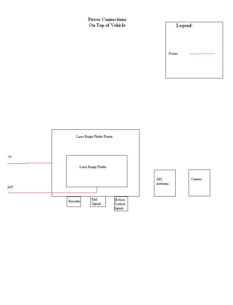
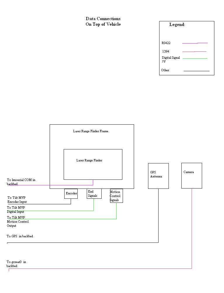
Vehicle Top Connections Diagram
Vehicle Top Power Diagram