|
|
For
participants only. Not for public distribution.
|
 |
Note #26
John Nagle |
A combination of passive and active stabilization should be sufficient to do the job.
Passive stabilization
Balance
The laser rangerfinder is mounted in a pitch-only gimbal. It's balanced,
so that it will swing freely in pitch. Balancing the unit also has the effect
of eliminating torques induced by linear accelerations. Shock mounts
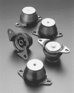 |
Typical rubber shock mounts These are small engine mounts from Lord Manufacturing. Shown as examples only, these specific mounts are for loads in the 100Kg range. |
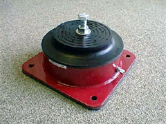 |
Air mount This air mount, from Qontrol Devices, can be adjusted by inflation. It allows more travel than the rubber shock mounts. It's oversized for our application; this unit can support 30 to 60Kg. It may not offer enough damping. |
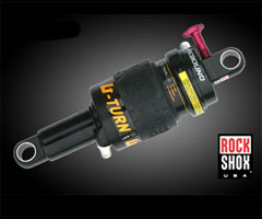 |
Bicycle shock absorber Compact units like this one from Rock Shox could be effective. They're adjustable in both damping and spring rate. The point-to-point mounting form is inconvenient. We might have to use six of them to form a Schrader platform. |
The goal of shock mounting is to reduce high-frequency pitch oscillation to no more than half a degree in pitch. "High frequency" here means above the frequency that the active stabilization unit can handle, which will probably be a few hertz.
This requires some engineering. We need to collect data to find out what
we need.
Active stabilization
Active stabilization is in pitch only, and is rather simple.
The sensors for active stabilization are one rate gyro, meaasuring pitch
rate, and the pitch servomotor encoder. The rate gyro is mounted at the
base of the unit, outboard of the shock mounts but inboard of the servoed
gimbal. The rationale is that we see chassis motion first at the unit
base. If we obtain inertial pitch rate information on the unit we're stabilizing,
we don't see pitch motions until they've forced their way through the
servomotor.
The stabilization servoloop merely servoes velocity in opposition to the
pitch velocities measured at the gimbal base. This opposes whatever pitch
motions are induced at the base. This velocity-only servo works because
the unit is balanced on the pitch axis.
Outside of the velocity servoloop, we need a second loop to control position.
This is a slower loop than the velocity loop. The position goal is relative
to the chassis, not the horizon.
A still slower loop determines the goal position. Its input comes from
the mapping system, which is continually trying to fill in the map out
to about 1.5x the stopping distance at the current speed.
So we're not actually trying to keep the unit locked relative to the horizon.
We don't have to. All we're doing is filtering out vibration, and letting
the mapping system direct the gaze.
Mounting and drive
 |
|
 |
 |
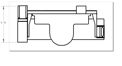
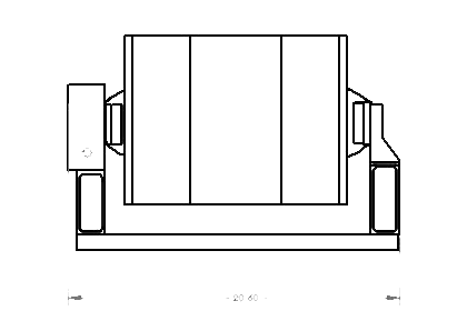
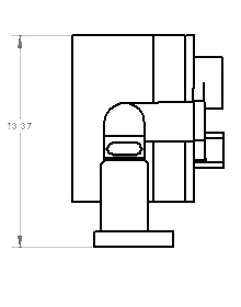
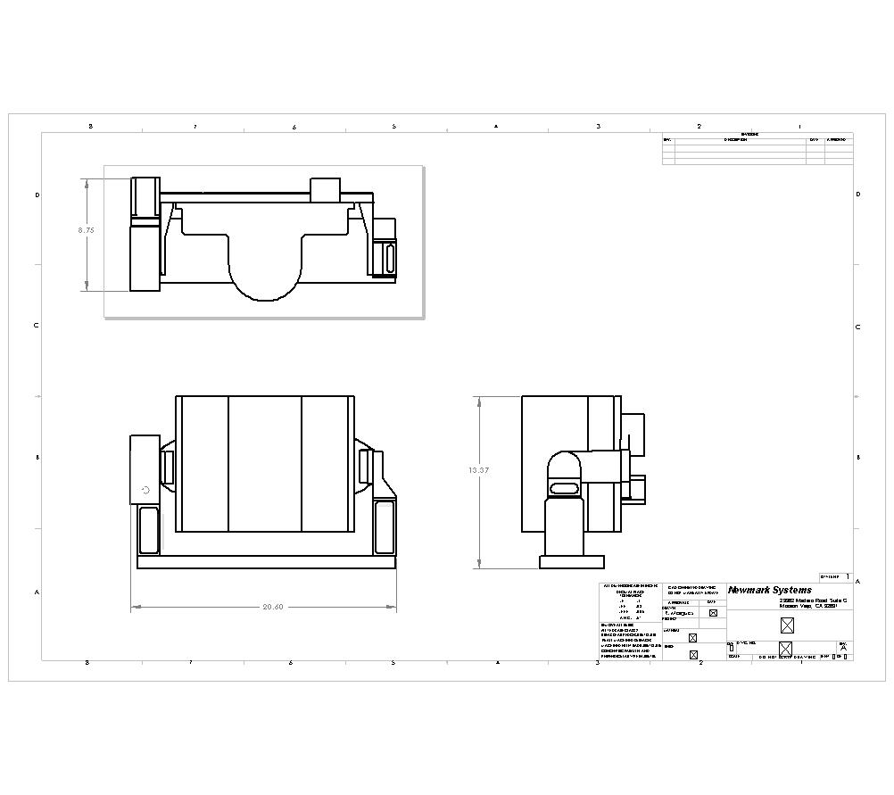
This is a rough sketch of a semi-custom tilt mount from Newmark, who quote about $6000, plus the cost of the motor and encoder. They're proceeding with a detailed design.